CN Electronics
Choosing the right AC/DC-Rectifier in 2026 requires more than comparing voltage ratings. Engineers must examine efficiency, ripple, heat, power factor, switching speed, and service conditions. A compact adapter may favor a single-phase bridge rectifier. A factory drive may require a three-phase controlled rectifier. Data-center power systems often demand active rectification and tighter harmonic management.
Dr. Bimal K. Bose, a widely respected power-electronics authority, defined the field clearly: “Power electronics is the technology associated with the conversion, control, and conditioning of electric power.” That principle remains highly relevant. A rectifier does not merely change alternating current into direct current. It also shapes the energy delivered to capacitors, batteries, motors, and sensitive digital circuits.
This guide examines the leading 2026 AC/DC-Rectifier types, including diode bridges, thyristor rectifiers, synchronous designs, active front ends, and Vienna rectifiers. Each option has trade-offs. Lower cost can mean higher ripple. Higher efficiency can increase control complexity. Smaller hardware may create difficult thermal paths.
Real-world details matter. A hot enclosure, a 400-volt bus, or a sudden load step can expose weaknesses that laboratory graphs hide. Some comparisons may appear too general. That is intentional. Application results depend on topology, cooling, switching frequency, and installation quality. Engineers should verify every selection through simulation, prototype testing, and documented measurements. No single rectifier wins everywhere. The best choice fits the load, environment, maintenance plan, and future power requirements.
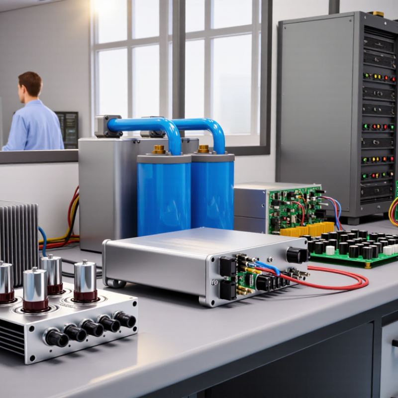
What Are the 2026 Top AC DC Rectifier Types?
AC-DC rectifiers convert alternating current into direct current for electronic equipment. An AC waveform changes direction repeatedly. A rectifier steers both half-cycles toward one output path. The result is pulsating DC, not perfectly smooth power. A capacitor, inductor, or regulator then reduces ripple and stabilizes voltage.
The single-phase bridge rectifier remains common in compact power supplies. It uses four diodes and works without a center-tapped transformer. For industrial loads, three-phase bridge rectifiers provide steadier output and better power handling. Controlled rectifiers use thyristors to adjust average DC voltage through firing-angle control. They suit motor drives and battery charging systems, although their input current can become less clean.
High-frequency designs may use Schottky or synchronous rectification to reduce conduction losses. This matters in low-voltage converters, where even a small voltage drop creates heat. Engineers select a type by checking input range, load current, switching frequency, thermal limits, and ripple requirements. Safety isolation also deserves careful review. A lower-cost topology may look efficient on paper but perform poorly in a warm enclosure. That distinction is easy to miss. No single rectifier wins every design. In practical testing, measurement often challenges the first calculation. A reliable design verifies diode temperature, transient response, and output ripple under changing loads.
An AC-DC rectifier converts alternating current into usable direct current. The process usually begins with an input filter and protection stage. A transformer may adjust voltage or provide electrical isolation. Diodes then conduct during each half-cycle, creating a pulsating DC waveform. A capacitor smooths the peaks, but ripple remains. It matters.
Common rectifier types include diode bridges, controlled thyristor rectifiers, active PWM rectifiers, and Vienna-style three-phase rectifiers. Diode bridges are simple, durable, and affordable, but their power factor can be modest. Thyristor designs regulate output well under heavy loads, although they can create more harmonic distortion. Active PWM circuits use high-speed switches, inductors, and feedback control. They can improve power factor and reduce current distortion. Vienna rectifiers suit efficient three-phase equipment, especially where compact power conversion is important.
In practical testing, engineers check more than output voltage. An oscilloscope reveals ripple during sudden load changes. A thermal camera exposes hot terminals and uneven cooling. Input current measurements show whether the circuit is polluting the supply. Safety depends on insulation, grounding, creepage distance, and verified protection controls. Efficiency claims also need careful interpretation. A rectifier may perform well at full load but lose efficiency during light-load operation. That weakness is easy to overlook. Designers should also consider acoustic noise, capacitor aging, switching stress, and service access. No design is perfect. A slightly larger rectifier can sometimes deliver steadier operation and fewer maintenance problems.
In 2026, bridge rectifiers remain a practical choice for chargers, control cabinets, and compact power supplies. They use four diodes to convert both AC half-cycles, improving output smoothness and transformer utilization.
Full-wave center-tapped rectifiers still serve low-voltage designs, especially when a suitable transformer is already available. Half-wave rectifiers cost less, but their ripple and transformer stress limit serious applications.
Active rectifiers are gaining attention where efficiency, power factor, and heat control matter. They replace passive diode action with controlled switching devices and sensors. Synchronous rectifiers can reduce conduction losses in low-voltage DC stages. Silicon carbide diodes also help high-frequency systems operate with lower recovery losses.
Still, advanced parts do not fix poor thermal design. That assumption can fail. Real installations expose wiring inductance, airflow problems, and unexpected load changes.
Tips:
Check temperature at the hottest diode, not only the enclosure surface. Measure ripple under the real load. Add suitable fusing, insulation spacing, and surge protection after reviewing applicable safety standards.
A bridge may look efficient on paper, yet its losses can become significant inside a sealed cabinet. Engineers should compare efficiency, cost, service access, and fault behavior before choosing a topology.
Sometimes, the simpler circuit survives longer.
In 2026, AC-DC rectifiers differ mainly in control method, switching speed, efficiency, and heat behavior. A diode bridge remains the simplest option for low-cost power supplies. It conducts automatically and needs little maintenance. However, its forward-voltage loss produces noticeable heat under heavy load. Ripple also increases when the filter capacitor is undersized.
Controlled silicon rectifiers suit high-power industrial converters and battery chargers. Their firing angle adjusts the DC output, but control circuits add complexity. Power-factor correction can improve input performance. Active rectifiers using MOSFETs switch faster and reduce conduction losses. They also support bidirectional energy flow in some systems. That flexibility demands careful firmware, sensing, and electromagnetic-interference control. More features mean more failure points.
Synchronous rectification replaces ordinary diodes with actively controlled switches. It can reduce losses in low-voltage, high-current outputs, especially inside compact equipment. High-frequency designs use smaller transformers and capacitors, but switching noise becomes harder to manage. In bench testing, temperature probes near the switch and transformer reveal problems that efficiency figures can hide. A practical comparison should measure ripple, standby consumption, thermal rise, and startup behavior. I once assumed the highest efficiency was always best. That view was incomplete. A slightly less efficient circuit may offer stronger overload protection and easier servicing. Cost, cooling space, load profile, and required isolation still influence the most reliable choice.
Typical full-load efficiency ranges for widely used AC-DC rectifier technologies. Actual performance varies with power level, switching frequency, cooling, input voltage, and control design.
Key differences: Diode bridges are simple and economical but usually provide limited power-factor correction. Thyristor rectifiers support high power and controllable output, although they introduce more input harmonics. Active PWM and Vienna rectifiers generally deliver higher efficiency, better power factor, and lower harmonic distortion, but require more complex control and switching hardware.
What Are the 2026 Top AC DC Rectifier Types?
Selecting the right AC-DC rectifier starts with the load, not the catalog. A single-phase diode bridge suits chargers, control panels, and small industrial supplies. It is simple, low-cost, and reliable. However, its input current can be narrow and highly peaked. That may increase harmonic distortion and stress the upstream wiring.
For higher power, a three-phase diode rectifier offers better current distribution and lower ripple. It fits motor drives, heating systems, and factory equipment with steady loads. A controlled thyristor rectifier adds adjustable DC voltage, making it useful for battery charging and process control. It responds more slowly than modern switching designs. That limitation matters during rapid load changes.
Active PWM rectifiers provide regulated power flow and improved power factor. They are strong candidates for data equipment, renewable-energy interfaces, and sensitive automation systems. Synchronous rectification can reduce conduction losses in low-voltage, high-current outputs. Thermal testing remains essential. A cool laboratory result may change inside a sealed cabinet at 45°C.
Check input voltage, output range, ripple limits, overload duration, isolation, and cooling space. Measure the real load profile, including startup surges. One common mistake is selecting by rated watts alone. It ignores harmonics and short overloads. No selection chart is perfect. Engineers should verify efficiency with actual cables, fans, and enclosure temperatures. Sometimes, a simpler diode design proves more dependable than a complex active circuit. The better choice is the one that remains stable when conditions become inconvenient.
| Rectifier Type | Typical Input | Typical Output Range | Typical Efficiency | Power Factor | Output Ripple | Best-Fit Applications | Key Selection Considerations |
|---|---|---|---|---|---|---|---|
| Single-Phase Half-Wave | Single-phase AC | Low-voltage DC; approximately 0.45 × RMS input voltage without filtering | 70–85% | Low; strong waveform distortion | High; ripple frequency equals the AC line frequency | Very low-power indicators, simple bias supplies, signal-level circuits | Lowest component count, but poor transformer utilization, high ripple, and limited usable power. |
| Single-Phase Full-Wave Center-Tapped | Single-phase AC with center-tapped transformer | Approximately 0.90 × RMS voltage of each half-winding without filtering | 80–92% | Low to moderate | Lower than half-wave; ripple frequency is twice the AC line frequency | Low-voltage linear supplies, analog circuits, battery charging | Good voltage utilization, but requires a center-tapped transformer and higher transformer copper usage. |
| Single-Phase Bridge Rectifier | Single-phase AC; four-diode bridge | Approximately 0.90 × RMS input voltage without filtering; near-peak DC with a capacitor filter | 85–96% | Moderate without power-factor correction | Twice the AC line frequency with a basic capacitor filter | Consumer power supplies, adapters, control equipment, general-purpose DC buses | Compact and economical; account for two diode forward-voltage drops and inrush current. |
| Three-Phase Six-Pulse | Three-phase AC | Approximately 1.35 × line-to-line RMS voltage | 90–97% | Typically 0.75–0.95, depending on load and filtering | Six times the AC line frequency before additional filtering | Industrial drives, welders, electroplating, medium-power DC systems | Higher power capability and lower ripple than single-phase designs, but creates characteristic input harmonics. |
| Controlled Thyristor Rectifier | Single-phase or three-phase AC | Adjustable DC output; voltage controlled by firing angle | 85–96% | Moderate to low at reduced output voltage | Medium to high; depends on pulse number and firing angle | Large battery chargers, DC motors, industrial heating, process control | Provides direct output control and regenerative options in some configurations, but has slower response and more harmonics. |
| Active PWM Rectifier | Single-phase or three-phase AC | Regulated DC bus, commonly 200–800 V in modern equipment | 94–99% | Typically 0.98–0.999 with suitable control | Low after switching and EMI filtering | Regenerative drives, high-performance power supplies, energy-storage interfaces | Excellent power-factor and bidirectional power-flow capability, with higher control, sensing, and EMI-filter complexity. |
| Vienna Three-Level Rectifier | Three-phase AC | Regulated high-voltage DC bus, commonly 600–900 V | 96–99% | Typically above 0.98 | Low differential ripple with appropriate control | Fast EV chargers, telecom rectifiers, data-center power systems, industrial front ends | High efficiency and low input distortion; generally unidirectional and requires careful neutral-point voltage control. |
| Multipulse Rectifier | Three-phase AC with phase-shifting transformer | High-power DC output; voltage depends on pulse number and transformer ratio | 94–98% | High, commonly 0.90–0.98 | Lower than six-pulse designs; characteristic ripple rises with pulse number | High-power drives, electrochemical plants, large industrial DC loads | Reduces selected low-order harmonics without active switching, but transformer size, cost, and weight are significant. |
| Synchronous MOSFET Rectifier | Usually low-voltage, high-frequency AC or transformer output | Typically below 100 V DC; application-dependent | 90–98% | Depends on the upstream power stage | Low with proper high-frequency filtering | Low-voltage server rails, USB-C power systems, telecom converters, battery-powered equipment | Replaces diode losses with controlled conduction losses; best suited to low-voltage, high-current outputs. |
| Power-Factor-Corrected Boost Front End | Single-phase AC after a diode bridge | Usually regulated around 380–420 V DC from universal mains | 93–98% | Typically above 0.95; can exceed 0.99 | Low input-current distortion with suitable control | Computing equipment, LED drivers, appliances, medical and industrial power supplies | Improves power quality and supports wide input voltage ranges, but adds an inductor, switch, diode, controller, and protection requirements. |
Typical values are design-range estimates for comparison only. Actual efficiency, power factor, ripple, voltage, thermal performance, and compliance depend on input voltage, load profile, switching frequency, semiconductor technology, transformer design, filtering, cooling, and control strategy.
It converts alternating current into direct current for electronic equipment. The output initially contains pulsating voltage.
Diodes guide both input half-cycles toward one output path. A capacitor or inductor then reduces voltage ripple.
It uses four diodes to convert single-phase AC. It does not require a center-tapped transformer.
It suits industrial loads needing steadier output and higher power handling. Its waveform usually has less ripple.
Thyristors change their firing angle to control average DC voltage. This approach suits motor drives and battery charging systems.
They use fast switches, inductors, and feedback control. They can improve power factor and reduce input-current distortion.
A small diode voltage drop can create noticeable heat at high current. Synchronous methods may reduce conduction losses.
They should check ripple, diode temperature, transient response, input current, and efficiency under changing loads. Test results may challenge calculations.
A circuit can appear efficient on paper but overheat inside a warm enclosure. Hot terminals and uneven cooling deserve attention.
No design is perfect. Input range, load current, isolation, frequency, ripple, and maintenance needs affect selection. A larger circuit may sometimes operate more steadily.
This article explains the role of the AC/DC-Rectifier in converting alternating current into stable direct current for electronic equipment, industrial systems, transportation, telecommunications, and renewable-energy installations. It introduces the basic conversion process, including rectification, voltage smoothing, regulation, and power-quality control, while showing how modern power systems use improved efficiency, thermal management, protection features, and intelligent control to support reliable operation.
The discussion reviews the leading AC-DC rectifier types expected in 2026, such as diode, controlled, active, modular, and high-frequency designs. It compares their efficiency, output control, power factor, size, cost, maintenance needs, and suitability for different loads. The article also provides practical guidance for selecting a rectifier according to input conditions, required voltage and current, energy-efficiency targets, operating environment, reliability expectations, and future expansion.