CN Electronics
Choosing the right AC/DC-Converter is more than matching an input voltage with an output rating. It affects safety, efficiency, thermal performance, and the service life of the entire device. A converter used inside a desktop controller may face different demands from one installed in a factory cabinet or medical instrument. The application matters.
Start with the electrical conditions. Check the full input range, required output voltage, maximum load current, startup behavior, and ripple limits. A 24 V, 5 A load needs more than a converter labeled “120 W” in a catalog. Headroom is important. Allow space for inrush current, temperature changes, and future expansion. A unit running continuously near its limit may become unnecessarily hot.
Physical details also deserve attention. Measure the enclosure before ordering. Confirm mounting holes, terminal spacing, airflow, and cable access. In one practical installation, a correctly rated converter failed to fit because its cooling fins touched the cabinet wall. Small oversights can create expensive delays.
Review efficiency curves, not only the headline efficiency figure. A product may reach 94% efficiency at full load but perform differently at light loads. Check protection features, including overvoltage, overcurrent, short-circuit, and thermal shutdown. Relevant safety certifications should match the target market and application. Documentation from an established manufacturer is valuable, but it should still be verified against the actual model.
There is no perfect choice.
Real systems change. Loads age, environments become warmer, and assumptions prove incomplete. For that reason, test the selected converter under realistic voltage, temperature, and load conditions before final approval. Careful selection is not about choosing the largest unit. It is about choosing a reliable balance of performance, safety, cost, and maintainability.
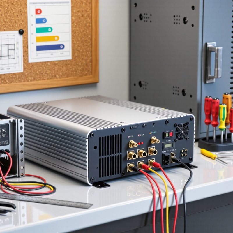
Choosing the right AC-DC converter starts with clear electrical requirements. Write down the required output voltage, current, power, and duty cycle before comparing products. Measure the load, rather than relying only on its label. A device needing 24 V and 2 A requires stable 24 V output and at least 48 W. Voltage must stay within the equipment’s tolerance. Excessive voltage can damage sensitive circuits. Insufficient voltage may cause resets or weak motor performance.
Leave operating margin. A converter running continuously at its maximum rating may become hot and age faster. In many installations, allowing 20–30% extra power is a practical target. Check startup current carefully. Motors, relays, and capacitive loads can draw several times their normal current for a short period. That brief surge still matters. Duty cycle describes how long the converter operates and how often it rests. Continuous operation demands stronger thermal performance than a ten-minute intermittent load.
Look beyond the wattage number. Confirm the AC input range, frequency, output regulation, protection features, and cooling method. A 100 W converter inside a sealed enclosure may perform worse than expected. Test it under the highest load and ambient temperature you expect. Watch the case temperature and output voltage. A rough calculation can mislead. I still recheck cable losses, because thin wires can reduce voltage at the load. The requirement may change after real testing. That is normal.
Matching input and output ranges is more than checking voltage labels. Start with the actual mains conditions at the installation site. A converter rated for 100–240 VAC may still require derating at low line, high temperature, or maximum load. Check frequency, inrush current, standby power, and transient tolerance. Small details matter.
IEC 62368-1 uses a hazard-based approach to evaluate electrical, thermal, and energy-related risks. The converter should support suitable insulation, creepage, clearance, and touch-current limits within the final equipment. Review reinforced or basic insulation requirements between input and output. Also examine overload, short-circuit, and abnormal-operation tests. A compliant-looking data sheet is not enough.
Output selection deserves equal care. Confirm voltage accuracy, ripple, dynamic response, and continuous current under real airflow conditions. Leave practical headroom instead of operating continuously at the limit. During bench testing, measure the converter after warm-up, not only when it is cold. I have seen a stable output drift after several hours. That result changed the design.
Keep test reports, component ratings, installation instructions, and safety approvals together. They help engineers trace every decision during verification. However, approval for a converter alone may not prove compliance in the finished product. The enclosure, wiring, connectors, fuses, and accessible parts can change the risk profile. Recheck the complete assembly. That step is easy to underestimate.
Choosing the right AC DC converter requires more than reading its maximum wattage. Efficiency usually ranges from 85% to 95%, depending on load, voltage, and temperature. An 85% converter wastes more energy than a 95% model. At 100W output, that difference can create about 12.4W of additional heat. Small enclosures feel it quickly. Not a minor detail.
Compare efficiency at realistic loads, not only at the listed peak. A converter rated 95% at full load may fall near 88% at 20W. Check input voltage, output current, ambient temperature, and cooling method. Datasheet graphs matter more than one headline number. In a bench test, place a wattmeter before the converter and an electronic load after it. Calculate efficiency by dividing output power by input power. Measure again after thirty minutes. Heat changes the result.
Thermal loss directly affects reliability and enclosure design. For 200W output at 90% efficiency, input power is about 222W, leaving 22W as heat. That heat needs a path through copper, airflow, or a heatsink. Keep the case below the specified temperature range. A five-degree margin is useful, though not always enough. I would question optimistic testing conditions. A cool laboratory and short cables can hide field losses. A 92% converter may reduce cooling demands, yet it can cost more and perform poorly at light loads. The real load profile deserves careful attention.
| Conversion Efficiency | Input Power for 100 W Output | Heat Loss at 100 W Output | Heat Loss at 500 W Output | Thermal Impact | Typical Selection Guidance |
|---|---|---|---|---|---|
| 85% | 117.65 W | 17.65 W | 88.24 W | High heat generation; generous ventilation or a heatsink may be required. | Suitable when cost, availability, or low-to-moderate power density is more important than energy consumption. |
| 88% | 113.64 W | 13.64 W | 68.18 W | Noticeable thermal load, especially in sealed enclosures or at high ambient temperature. | Acceptable for general-purpose equipment when operating hours and enclosure size are moderate. |
| 90% | 111.11 W | 11.11 W | 55.56 W | Moderate heat generation; airflow may be needed at higher output power. | A practical baseline for many compact AC DC power-conversion applications. |
| 92% | 108.70 W | 8.70 W | 43.48 W | Lower thermal stress and reduced cooling requirements compared with 85–90% designs. | Well suited to continuously operating equipment, limited-enclosure airflow, and higher power density. |
| 93% | 107.53 W | 7.53 W | 37.63 W | Low heat generation; improves component life and helps maintain a lower internal temperature. | A strong choice for energy-sensitive systems with long daily operating times. |
| 95% | 105.26 W | 5.26 W | 26.32 W | Very low relative heat loss, although cooling may still be necessary at high power. | Preferable for high-duty-cycle equipment, compact enclosures, energy-efficient designs, and reduced operating costs. |
How to Choose the Right AC DC Converter?
Evaluate Power Factor, Ripple, Regulation, Isolation, and EMI Performance
Choosing an AC DC converter starts with the real load, not the advertised wattage. A laboratory load may draw 80 watts, but startup current can briefly double that demand. Leave practical headroom. Power factor matters when equipment operates continuously or shares a circuit with other loads. A poor value increases input current and heating. However, a high power factor does not guarantee efficient operation. Check efficiency at typical, low, and peak loads.
Ripple should be measured at the converter output with a short ground connection. Long oscilloscope leads can create false spikes. Test under changing loads, because a quiet waveform at steady load may become noisy during motor or relay switching. Regulation should cover both input-voltage variation and load changes. A converter that performs well at room temperature may drift inside a warm enclosure. I have seen datasheet limits look reassuring until cable resistance exposed the weakness.
Isolation requires more than a simple voltage rating. Verify reinforced or functional isolation needs, creepage, clearance, and leakage current for the finished assembly. EMI performance also deserves testing before the enclosure is finalized. Observe conducted noise at the input and radiated emissions around cables, vents, and switching nodes. Keep wires short. Add filtering only after identifying the noise path; extra components can increase cost, losses, and even resonance. Independent verification is valuable, because prototype measurements are often incomplete and human error remains possible.
Start with the load. Estimate output voltage, current, startup surge, standby demand, and allowed ripple. A converter for a small sensor rarely needs the same topology as a motor controller.
For low-power isolated designs, a flyback topology often reduces component count and cost. Higher power levels may benefit from forward or resonant topologies, especially when efficiency and heat are critical. Check transient performance with an electronic load, not only at steady state. A brief voltage dip can reset sensitive digital equipment. Real testing reveals weaknesses.
Protection features should match the operating environment. Overvoltage, overcurrent, short-circuit, and overtemperature protection are essential safeguards. Add input surge protection and controlled inrush limiting when the converter connects to long cables or unstable mains. Electromagnetic interference also deserves attention; a cheaper circuit may require a larger filter later. Cost can move rather than disappear. Leave thermal margin, and inspect the hottest component after several hours at full load. I have seen designs pass bench tests but fail inside a warm enclosure. That result is easy to underestimate. Reliability improves when protection thresholds, component ratings, isolation distance, and cooling are reviewed together. Redundant protection is useful, but excessive circuitry can increase failure points and maintenance effort. Choose deliberately, then test the unpleasant conditions.
Check actual mains voltage, frequency, temperature, load, and startup current. A 100–240 VAC rating may still need derating. Measure low-line operation carefully.
Startup demand can briefly double the normal load. Leave practical current and thermal margin. Continuous operation at the limit often exposes hidden weaknesses.
Measure voltage accuracy, ripple, regulation, and dynamic response. Test after warm-up, not only when cold. A stable output may drift after several hours.
Use a short oscilloscope ground connection. Long leads can create false spikes. Test during motor, relay, or electronic-load switching. Steady readings can deceive.
Check basic or reinforced insulation, creepage, clearance, and touch current. Review the complete assembly, including wiring, connectors, fuses, and accessible surfaces. The converter alone is not the final product.
Check power factor during continuous operation and shared-circuit use. Measure efficiency at low, typical, and peak loads. A high power factor does not guarantee low heating.
Review overvoltage, overcurrent, short-circuit, and overtemperature protection. Consider surge protection and controlled inrush limiting for long cables. More circuitry is not always better.
Start with voltage, current, surge, ripple, standby demand, and heat limits. Lower-power isolated designs may use simpler topologies. Higher power may require better efficiency and cooling.
Test conducted noise before finalizing the enclosure. Check radiated emissions around cables, vents, and switching areas. Add filtering after identifying the noise path.
Keep test reports, component ratings, installation instructions, and safety approvals together. Verify the finished equipment against IEC 62368-1 requirements. Paperwork alone cannot reveal every assembly risk.
Choosing the right AC/DC-Converter begins with clearly defining the application’s voltage, current, power, and duty-cycle requirements. Confirm that the converter’s input and output ranges match the system specifications and support the relevant IEC 62368-1 safety requirements. It is also important to compare conversion efficiency, typically within the 85–95% range, because lower efficiency creates greater thermal losses and may require additional cooling.
Beyond basic ratings, evaluate power factor, output ripple, voltage regulation, electrical isolation, and electromagnetic interference performance. These factors directly affect system stability, safety, and compatibility with other equipment. The converter topology should be selected according to the load profile, cost limitations, space constraints, and expected service life. Finally, review protection features such as overvoltage, overcurrent, short-circuit, overtemperature, and surge protection. A balanced assessment of performance, reliability, safety, and total operating cost will help ensure the selected converter meets both immediate requirements and long-term application goals.